Spot and projection welders
- 80 to 315 kVA
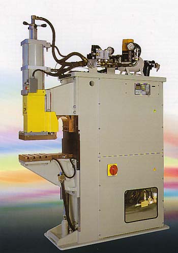 |
MAIN WELDER FEATURES
|
TECHNICAL DATA
| Nominal power at 50% | 80 | 100 | 125 | 160 | 200 | 250 | 315 | |
| Body | A-B | A-B | A-B | A-B-C | A-B-C | B-C | B-C | |
| Spot welder | • | • | • | - | - | - | ||
| Projection welder | • | • | • | • | • | • | • | |
| Maximum welding power * | kVA | 200 | 280 | 340 | 420 | 560 | 750 | 970 |
| Short circuit current * | kA | 30 | 35 | 39 | 53 | 63 | 75 | 88 |
| Maximum welding current on steel * | kA | 24 | 28 | 31 | 42 | 50 | 60 | 70 |
| Thermal current 100% | A | 6800 | 7000 | 8400 | 11300 | 12800 | 14200 | 16200 |
| No load secondary voltages | V | 8.3 7.5 6.8 6.1 |
10 8.9 8 7.1 |
10.5 9 8.2 7.4 |
10 8.9 8 7.1 |
11.1 10 8.9 8 |
12.5 11.1 10 8.9 |
13.8 12.5 11.1 10 |
| Supply voltage 50Hz ** | V | 400 | 400 | 400 | 400 | 400 | 400 | 400 |
| Cables section L=30 m | mm2 | 70 | 95 | 2 x 50 | 2 x 70 | 2 x 95 | 2 x 120 | 2 x 150 |
| Delayed fuses | A | 160 | 200 | 250 | 315 | 400 | 500 | 630 |
| Cylinder | N°/daN | 4/736 6/1206 7/1885 |
4/736 6/1206 7/1885 |
6/1206 7/1885 8/3388 |
6/1206 7/1885 8/3388 9/2945 |
6/1206 7/1885 8/3388 9/2945 |
7/1885 8/3388 9/2945 10/5509 |
7/1885 8/3388 9/2945 10/5509 |
| Compressed air supply | bar | 6.5 | 6.5 | 6.5 | 6.5 | 6.5 | 6.5 | 6.5 |
| Air supply hose | mm | 25 | 25 | 25 | 25 | 25 | 25 | 25 |
| Water cooling | l/min | 8 | 8 | 10 | 10 | 10 | 12 | 12 |
| Water cooling hose | mm | 25 | 25 | 25 | 25 | 25 | 25 | 25 |
* Values subject to variations according to frame and L and D lengths
** Different voltages and frequencies on demand
AVAILABLE ON DEMAND:
- Rotary selector for recalling the welding programs.
- Insulated serial interface RS232, enabling the connection with a serial printer or a personal computer for production data recording.
- Prismatic stem cylinder in tempered steel and roller guide.
- Additional foot control to recall program No. 2 (not available with rotary selector recall).
- Two-hand safety control on pedestal, adjustable height (standard on projection welders).
- Proportional valve.
- Pneumatic circuit with low force squeeze and forging.
MAIN WELDER CONFIGURATIONS
| Frame type | A | B | C | ||||
| Arms length D | mm | 250 | 400 | 250 | 400 | 400 | 600 |
| Cylinder | N° | 4-6-7 | 4-6 | 6-7-8-9 | 6-7-8-9 | 8-9-10 | 8-9 |
| Projection plates dimensions slots number/centreline |
mm |
150x200 |
150x200 |
200x200 |
250x250 |
380x380 |
250x250 |
| Frame type | A | B | C | ||||||
| Arms length L | mm | 500 | 800 | 800 | 1000 | 1500 | 800 | 1000 | 1600 |
| Cylinder | N° | 4-6 | 4 | 4-6-7 | 4-6 | 4 | 6-7-8-9 | 6-7 | 6 |
| Electrode holder diameter | mm | 32 | 32 | 32 | 32 | 32 | 40 | 40 | 40 |
| Arms diameter | mm | 80 | 80 | 100 | 100 | 100 | 120 | 120 | 120 |
The combinations of: structure, power, cylinder and lengths L - D are to be agreed with our Technical Department
CYLINDERS
| Type | N° | 4 | 6 | 7 | 8 | 9 | 10 |
| Diameter | mm | 125 | 160 | 200 | 200x2 | 250 | 250x2 |
| Force at 6 bar at 1 bar |
daN |
736 |
1206 |
1885 |
3388 |
2945 |
5509 |
| Stroke total adjustable |
mm |
100 |
100 |
150 |
150 |
150 |
150 |
| Cilindric stem diameter | mm | 70 | 90 | 100 | 100 | - | - |
| Prismatic stem | mm | - | 86x86* | 86x86* | 86x86* | 96x96 | 96x96 |
* On request